Projects:Quadcopter drone modding
| Description | Cheap, hackable quadcopter drone toys |
|---|---|
| Has website | irc://irc.hackint.eu/drones "irc" has not been listed as valid URI scheme. |
| Persons working on | Aczid, D0b |
| Self-organized sessions | create self-organized session |
| Tags | drone, quadcopter, electronics, hardware, software, arduino, rad1o |
| Located at village | Village:Idiopolis |
| Other projects... ... further results | |
Contents
Introduction
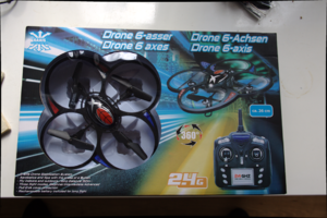
We bought a bunch of these JXD 393 quadcopter drones at an auction. They appear to be returned items from a local outlet store chain. Some of them needed a bit of refurbishing, but we sold over 50 that flew at CCCamp2015. We did so at no profit to ourselves (20 euros CIB), with a liberal return/exchange policy.
They don't have fancy features like a camera, but they are easy to fly, very sturdy and can carry about 15 extra grams of payload without removing parts.
| Summary of instructions |
|---|
After both the drone and the remote are powered on, the throttle must be toggled (left stick up-down) to complete the binding from the remote. The quadcopter has an orientation: the red LEDs are on the rear side, enclosing the propellor marked with CE logos and such. The 'joysticks' (gimbals) control the drone as follows:
Each axis can be adjusted via its adjacent 'trim' buttons to compensate for any deviation in balance. The shoulder buttons work as follows:
To recalibrate the gyroscope/accelerometer: hold the right shoulder button and move both gimbals towards the bottom left. |
Hardware
The box contains a 26 cm diameter quadcopter drone which includes a 3.7V 380mAh LiPo battery pack (for about 10 minutes of flight), a remote control that requires 4 AA batteries (not included), a set of replacement propellors, a screwdriver that fits the tiny screwholes and a USB charging cable. The MCU inside the drones is an STM8S005K6 and the radio chips on both the drone and the remote are Beken BK2421 (a clone of the Nordic NRF24l01). The gyro/accelerometer is an MPU6050.
Drone
Read Out Protection
The STM8 has some write protection, but the Memory Access Security System (MASS) and User Boot Code (UBC) protection features are only provided as a convenience/safety measure to prevent the unwanted overwriting of Flash or EEPROM. The only actual security measure is Read Out Protection (ROP), and this is indeed activated on the chip in the JXD393. ROP prevents reading or writing of any of the memories and disabling it will trigger a chip erase procedure. More details can be found in the RM0016 datasheet.
This means that any reprogramming of the stm8 will require erasing your firmware: hold off until we have proper firmware sources or manage to dump a recovery image!
On that note, we are looking for experienced quadcopter software developers to develop a replacement firmware. Please get in touch through our Talk page or IRC. Of course we are also very interested to get in touch with people who are experienced in breaking copy protections in MCUs.
Reprogramming
So while we can't dump the original firmware, we are still able to flash our own firmware onto the drones; for examples we can look at Afrowii, an STM8 port of Multiwii. I've verified with an ST-link programmer that you can program the boards after resetting the options for ROP using STVP (windows only). I've also found some instructions on how to get started programming STM8 boards in Linux, and I was able to enable/disable ROP and program all the memories after a few simple patches to stm8flash (which got merged upstream since).
I've begun work on an alternative firmware. So far it can work the LEDs and seems to have a working SPI driver and PWM control thanks to the standard library from ST, as well as my own bitbanging driver for the I2C bus to the MPU6050, and some nRF24l01 code for the stm8 by LonelyWolf that I've used to test the SPI connection to the BK2421.
Continue at your own risk
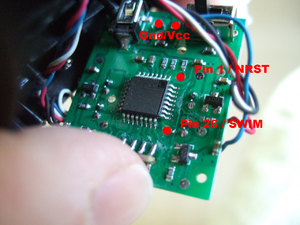
Pin 1 and 26 are used to debug and flash the chip over the Single Wire Interface Module (SWIM) interface. Here I've highlighted the test pads that lead to these pins (on a picture originally by SeByDocKy who wrote the RCgroups forum review containing a teardown of the JXD393).
The placement of these pads on the bottom of the PCB (facing numerous holes in the frame) makes them ideal to attach some dupont wires which can stick out of the drone while completely assembled and act as a programming/debugging interface.
MCU pin routing
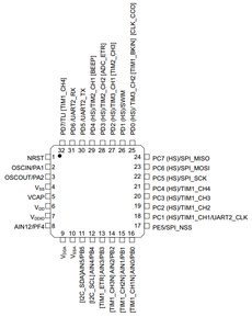
The pinout of the chip is as follows.
I think I managed to recover the routing for all the signals on the PCB:
 Pin  1: NRST (for our debugging interface)
 Pin  2: SCLK to MPU6050 through a via under the chip
 Pin  3: SDA to MPU6050 through a via under the chip
 Pin  4: GND
 Pin  5: regulator capacitor
 Pin  6: VCC, also CS to MPU6050 through a via shared with pin 7
 Pin  7: VCC, also CS to MPU6050 through a via shared with pin 6
 Pin  8: GND/NC
 Pin  9: VCC
 Pin 10: Analog GND, also CLKIN to MPU6050 through a via under the chip, shared with a via to the left of it
 Pin 11: GND/NC
 Pin 12: GND/NC
 Pin 13: GND/NC
 Pin 14: CE to Bk2421 through a via under the chip
 Pin 15: GND to Bk2421 through a via under the chip and another one on top (wish this was the IRQ)
 Pin 16: Motor 1 transistor output behind 1MOhm resistor through 2 vias
 Pin 17: GND/NC
 Pin 18: Motor 2 transistor through 2 vias (TIM1CH1)
 Pin 19: Motor 1 transistor (TIM1CH2)
 Pin 20: GND/NC
 Pin 21: SPI CSN to Bk2421 CSN pin
 Pin 22: SPI SCK to Bk2421 SCK pin
 Pin 23: SPI MOSI to Bk2421 MOSI pin
 Pin 24: SPI MISO from Bk2421 MISO pin
 Pin 25: GND/NC
 Pin 26: SWIM (for our debugging interface)
 Pin 27: Motor 4 transistor (TIM3CH1)
 Pin 28: Motor 3 transistor (TIM2CH2)
 Pin 29: GND/NC
 Pin 30: GND/NC
 Pin 31: GND/NC
 Pin 32: LEDs transistor through a via
There are 4 test pads for each of the LEDs, but they are controlled through a transistor connected to resistors on all the grounded sockets on the top of the board, where plugs on thin wires connect to the LEDs in the top part of the frame. The pads for the Beken daughterboard are connected to the SPI bus, which you might also manage to add more stuff to.
Remote control
I sniffed the SPI bus inside the remote control using a logic analyzer to recover the commands sent to the radio chip. From the trace it is clear that these are indeed the Beken clone chips and not Nordic RF originals, because they employ a bank switch command sequence not supported by the original and these extra registers are programmed with unexplained values that mostly conform to the Beken datasheet. Interestingly, some of the values used to reprogram the bank 1 registers partially differ from those endorsed by the datasheet (most notably in their endianness). While most of these mistakes can be fixed and still allow the drone to be paired, fixing the 'new feature' register 0xd in particular breaks something that prevents the drone from pairing with the remote.
Once initialization of the radio transmitter is completed, the remote starts sending control packets to the drone using its control channel address and waits to see an ACK. This was likely done so that in the case of an intermittent power failure, control can quickly be regained without having to re-pair the drone. If an ACK was not received after 30 tries, the remote switches to its pairing address and transmits a pairing packet containing its control channel address (as well as a few other bytes with a so far unknown meaning). This packet gets ACKed, and once that ACK is received the remote switches back to its control channel address and starts sending control packets without waiting for ACKs. If the ACK fails to arrive, 30 more control packets are tried before another pairing attempt. All packets have a payload of 9 bytes which includes a simple 1 byte CRC.
Arduino sketch
This sketch is based on work by Dzl and the DeviationTX project. This open source software project to repurpose off the shelf RC remotes also supports the JXD393 drone and names its protocol as 'SkyWlkr', a variant of 'yd717'. They also note the strangeness of the bytes written to the Beken registers in their comments, which I've copied throughout.
More background on the original Nordic RF chips and how to use them is available on the ArduinoInfo.Info WIKI. I've used the RadioHead arduino library to get access to some of its convenience functions for SPI as well as its register definitions. In the end I did not get my off the shelf clones to work (probably due to power issues) so I soldered leads to a desoldered Beken daughterboard as found in the drone/remote like Dzl did, but used the wire coloring like on the wiki.
There's probably still a serious bug in here because I never get an RX flag after pairing like the trace shows, only a TX flag when sending a packet. It works regardless, though.
| Example sketch |
|---|
// Arduino sketch to control JXD 393 quadcopter drones (and maybe similar drones)
// Pieced together from DeviationTX source code, the "hacking quadcopter drones" software and my own SPI trace
// Most of the comments on SPI commands were taken directly from DeviationTX

#include <SPI.h>
#include <RH_NRF24.h>

// the default id, or just the one for my remote?
uint8_t rx_tx_address[5] = {0xf8, 0x8f, 0xd1, 0x11, 0xc1};
// anything goes, just make sure it ends in 0xc1(?)
//uint8_t rx_tx_address[5] = {0x13, 0x33, 0x33, 0x37, 0xc1};
uint8_t bind_address[5] = {0x65, 0x65, 0x65, 0x65, 0x65};

#define PAYLOADSIZE 9
#define RF_CHANNEL 0x3C

// chip enable, slave select pins
RH_NRF24 nrf_driver(8,10);

uint8_t status_byte;

boolean init_nrf(){
  nrf_driver.init();
  status_byte = nrf_driver.spiReadRegister(RH_NRF24_REG_07_STATUS);
  nrf_driver.spiWriteRegister(RH_NRF24_REG_00_CONFIG, RH_NRF24_EN_CRC | RH_NRF24_PWR_UP);
  nrf_driver.spiWriteRegister(RH_NRF24_REG_01_EN_AA, 0x3F); // auto acknowledgement on all data pipes
  nrf_driver.spiWriteRegister(RH_NRF24_REG_02_EN_RXADDR, 0x3F); // enable all data pipes
  nrf_driver.spiWriteRegister(RH_NRF24_REG_03_SETUP_AW, 0x03); // 5-byte RX/TX address
  // deviation TX
  //nrf_driver.spiWriteRegister(RH_NRF24_REG_04_SETUP_RETR, 0x1A); // 500uS retransmit t/o, 10 tries
  // sniffed
  nrf_driver.spiWriteRegister(RH_NRF24_REG_04_SETUP_RETR, 0x3F); // delay 4 ms, up to 15 tries
  nrf_driver.spiWriteRegister(RH_NRF24_REG_05_RF_CH, RF_CHANNEL); // channel 3c
  nrf_driver.spiWriteRegister(RH_NRF24_REG_06_RF_SETUP, 0x07); // high gain, ~5dBm, 1Mbps
  nrf_driver.spiWriteRegister(RH_NRF24_REG_07_STATUS, 0x07); // clear status register
  nrf_driver.spiWriteRegister(RH_NRF24_REG_08_OBSERVE_TX, 0x00);
  nrf_driver.spiWriteRegister(RH_NRF24_REG_09_RPD, 0x00);
  nrf_driver.spiWriteRegister(RH_NRF24_REG_0C_RX_ADDR_P2, 0xC3); // LSB byte of pipe 2 receive address
  nrf_driver.spiWriteRegister(RH_NRF24_REG_0D_RX_ADDR_P3, 0xC4);
  nrf_driver.spiWriteRegister(RH_NRF24_REG_0E_RX_ADDR_P4, 0xC5);
  nrf_driver.spiWriteRegister(RH_NRF24_REG_0F_RX_ADDR_P5, 0xC6);
  nrf_driver.spiWriteRegister(RH_NRF24_REG_11_RX_PW_P0, PAYLOADSIZE); // bytes of data payload for pipe 1
  nrf_driver.spiWriteRegister(RH_NRF24_REG_12_RX_PW_P1, PAYLOADSIZE);
  nrf_driver.spiWriteRegister(RH_NRF24_REG_13_RX_PW_P2, PAYLOADSIZE);
  nrf_driver.spiWriteRegister(RH_NRF24_REG_14_RX_PW_P3, PAYLOADSIZE);
  nrf_driver.spiWriteRegister(RH_NRF24_REG_15_RX_PW_P4, PAYLOADSIZE);
  nrf_driver.spiWriteRegister(RH_NRF24_REG_16_RX_PW_P5, PAYLOADSIZE);
  nrf_driver.spiWriteRegister(RH_NRF24_REG_17_FIFO_STATUS, 0x0); // Just in case, no real bits to write here
  nrf_driver.spiWriteRegister(RH_NRF24_REG_1C_DYNPD, 0x3F); // Enable dynamic payload length on all pipes

  // this sequence is neccessary for module from stock tx
  nrf_driver.spiReadRegister(RH_NRF24_REG_1D_FEATURE);
  nrf_driver.spiWrite(RH_NRF24_COMMAND_ACTIVATE, 0x73);
  nrf_driver.spiReadRegister(RH_NRF24_REG_1D_FEATURE);
  nrf_driver.spiWriteRegister(RH_NRF24_REG_1C_DYNPD, 0x3F); // Enable dynamic payload length on all pipes
  nrf_driver.spiWriteRegister(RH_NRF24_REG_1D_FEATURE, 0x07); // set feature bits on


  nrf_driver.spiBurstWriteRegister(RH_NRF24_REG_0A_RX_ADDR_P0, bind_address, 5);
  nrf_driver.spiBurstWriteRegister(RH_NRF24_REG_10_TX_ADDR, bind_address, 5);


  // Check for Beken BK2421/BK2423 chip
  // It is done by using Beken specific activate code, 0x53
  // and checking that status register changed appropriately
  // There is no harm to run it on nRF24L01 because following
  // closing activate command changes state back even if it
  // does something on nRF24L01
  nrf_driver.spiWrite(RH_NRF24_COMMAND_ACTIVATE, 0x53); // magic for BK2421 bank switch

  Serial.println("Trying to switch banks");
  if(nrf_driver.spiReadRegister(RH_NRF24_REG_07_STATUS) & 0x80){
    Serial.println("BK2421 detected");
    // Beken registers don't have such nice names, so we just mention
    // them by their numbers
    // It's all magic, eavesdropped from real transfer and not even from the
    // data sheet - it has slightly different values
    nrf_driver.spiBurstWriteRegister(0x00, (uint8_t*) "\x40\x4b\x01\xe2", 4);
    nrf_driver.spiBurstWriteRegister(0x01, (uint8_t*) "\xc0\x4b\x00\x00", 4);
    nrf_driver.spiBurstWriteRegister(0x02, (uint8_t*) "\xd0\xfc\x8c\x02", 4);
    // sniffed
    nrf_driver.spiBurstWriteRegister(0x03, (uint8_t*) "\x99\x00\x39\x21", 4);
    // datasheet
    //nrf_driver.spiBurstWriteRegister(0x03, (uint8_t*) "\x99\x00\x39\x41", 4);
    // sniffed
    nrf_driver.spiBurstWriteRegister(0x04, (uint8_t*) "\xd9\x96\x82\x1b", 4);
    // datasheet
    //nrf_driver.spiBurstWriteRegister(0x04, (uint8_t*) "\xd9\x9e\x86\x0b", 4); // (high power)
    // nrf_driver.spiBurstWriteRegister(0x04, (uint8_t*) "\xd9\x9e\x86\x21", 4); // (single carrier mode)
    // disable RSSI
    nrf_driver.spiBurstWriteRegister(0x05, (uint8_t*) "\x24\x06\x7f\xa6", 4);
    // sniffed
    nrf_driver.spiBurstWriteRegister(0x0C, (uint8_t*) "\x00\x12\x73\x00", 4);
    // datasheet
    //nrf_driver.spiBurstWriteRegister(0x0C, (uint8_t*) "\x00\x73\x12\x00", 4);
    // sniffed
    nrf_driver.spiBurstWriteRegister(0x0D, (uint8_t*) "\x46\xb4\x80\x00", 4);
    // datasheet
    // This does not work
    //nrf_driver.spiBurstWriteRegister(0x0D, (uint8_t*) "\x00\x80\xb4\x36", 4);
    // sniffed ??
    nrf_driver.spiBurstWriteRegister(0x04, (uint8_t*) "\xdf\x96\x82\x1b", 4);
    nrf_driver.spiBurstWriteRegister(0x04, (uint8_t*) "\xd9\x96\x82\x1b", 4);
  } else {
    Serial.println("NRF24L01 detected");
  }
  nrf_driver.spiWrite(RH_NRF24_COMMAND_ACTIVATE, 0x53); // switch bank back
  nrf_driver.printRegisters();
  delay(250);
}

uint8_t crc(uint8_t* bytes, size_t len){
  uint8_t checksum = 0;
  for(size_t i = 0; i < len; i++){
    checksum += bytes[i];
  }
  return ~checksum;
}

typedef union {
  struct {
    uint8_t throttle;
    uint8_t rudder;
    uint8_t rudder_trim;
    uint8_t elevator;
    uint8_t aileron;
    uint8_t elevator_trim;
    uint8_t aileron_trim;
    uint8_t flag;
    uint8_t crc;
  } fields;
  uint8_t bytes[9];
} drone_cmd_t;

drone_cmd_t active_cmd;

void send_drone_cmd(uint8_t *cmd, boolean wait){
  cmd[8] = crc(cmd, 8);
  status_byte = 0;
  digitalWrite(8, false);
  nrf_driver.spiCommand(RH_NRF24_COMMAND_FLUSH_TX);
  nrf_driver.spiBurstWrite(RH_NRF24_COMMAND_W_TX_PAYLOAD, cmd, 9);
  nrf_driver.spiWriteRegister(RH_NRF24_REG_00_CONFIG, RH_NRF24_EN_CRC | RH_NRF24_PWR_UP);
  digitalWrite(8, true);
  if(wait){
    while(!(status_byte & (RH_NRF24_RX_DR | RH_NRF24_TX_DS | RH_NRF24_MAX_RT))){
      status_byte = nrf_driver.spiReadRegister(RH_NRF24_REG_07_STATUS);
    }
  }
  nrf_driver.spiWriteRegister(RH_NRF24_REG_07_STATUS, 0x7f);
}

#define MAX_TRIES 30

boolean bind(){
  nrf_driver.spiBurstWriteRegister(RH_NRF24_REG_0A_RX_ADDR_P0, bind_address, 5);
  nrf_driver.spiBurstWriteRegister(RH_NRF24_REG_10_TX_ADDR, bind_address, 5);
  memcpy(active_cmd.bytes, rx_tx_address, 5);
  active_cmd.bytes[4] = 0x56;
  active_cmd.bytes[5] = 0xaa;
  active_cmd.bytes[6] = 0x40;
  active_cmd.bytes[7] = 0x00;

  for(uint8_t tries = 0; tries < MAX_TRIES; tries++){
    send_drone_cmd(active_cmd.bytes, true);
    delay(5);
    //if(status_byte & RH_NRF24_RX_DR){
    if(status_byte & 0x20){ // because I never got the ack(?) I'm using this instead
      delay(750);
      nrf_driver.spiBurstWriteRegister(RH_NRF24_REG_0A_RX_ADDR_P0, rx_tx_address, 5);
      nrf_driver.spiBurstWriteRegister(RH_NRF24_REG_10_TX_ADDR, rx_tx_address, 5);
      Serial.println("done!");
      return true;
    }
    Serial.print(".");
  }
  Serial.println("failed :(");
  return false;
}

// TODO test
#define FLAG_FLIP 0x0f
// Only tested this one
#define FLAG_LEDS_OFF 0x10
#define FLAG_PICTURE 0x20
#define FLAG_VIDEO 0x40
#define FLAG_HEADLESS 0x80

void setup(){
  Serial.begin(115200);
  init_nrf();
  while(!bind()){
  }
  memcpy(active_cmd.bytes, "\x00\x80\x40\x80\x80\x40\x40\x00", 8);
  active_cmd.fields.throttle=0x65;
  //active_cmd.fields.rudder=0x40;
  //active_cmd.fields.flag |= FLAG_LEDS_OFF;
}

void loop(){
  send_drone_cmd(active_cmd.bytes, false);
  delay(15);
}
|
The end / not the end
We sold all our stock lot by the end of camp. You can buy this type of drone from China at Aliexpress, the european outlet store Action or perhaps other retailers as well as through auction sites.
A user in our IRC channel commented that the same MCU is also used in the "Top Selling X6" model of drones, but they have not shared other details about its hardware.
We managed to break even and cover our expenses, make out with a nearly complete reverse engineering of the quadcopters at a hardware level, get a lot of people a new toy and can hope to see some neat hardware/software hacks for them to come around. Next to that, nearly all of the broken motors and discarded frames got used after we donated them to Session:HEBOCON.
I've heard there was some activity with regards to dumping the MCU at the camp, but never got a direct source for that rumor after it came to me. If you did this and had any results you would like to share (privately) I would be thrilled to hear from you!
Finally, if you happen find toys that are similarly hackable, it would be great if you could share your findings with the community like we did. Fly safely!


