From Camp 2011 Public Wiki
| Laser Tag | |
|---|---|
| A project to create a Laser Tag add-on m0dul for the r0ket/CCC Camp badge. | |
| Contact | User:robfitz |
| People | Robfitz |
The challenge is to create a DIY Laser Tag system that uses the r0ket badge for operation. During the period of camp we will design and build the electronics, hardware and software.
Contents |
Components
- TSAL6100
- Infrared Emitting Diode
- TN0106
- MOSFET
- TSOP348
- Infrared Receiver Module
- ISD1740
- Voice Record & Playback, 40 Seconds
- AS03608MR
- Speaker
- OPL8A
- Plano-Convex Lens 40mm Diameter, 180mm Focal Length
Timeline
Pre Camp
Selection of components and researching circuit operation. Design initial schematic and layout single sided PCB, no time to etch or test before camp.
Day 0
Wired up the gun section of the circuit using a breadboard, corrected the use of the pull-up on the input of the MOSFET (should have been a pull-down).
Day 1
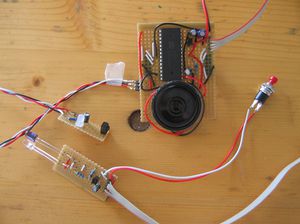
After a day of assembling I've come up with the following prototype m0dule which is soldered on to strip board. The schematic can be downloaded from my site in pdf format.The initial smoke test with the r0ket was OK. It seems that the default firmware might drive or have pull-ups on some of the GPIO pins, which causes the IR LED to fire constantly which might burn it out. So I'm going to limit my until I've check code.
I went to the talk on the r0ket badge and talked with some of the project participants afterwards. I'm going to spend some time with them tomorrow in there village Fpletzvillage.
Day 2
I had a late start working on the Laser Tag m0dul today, as I was helping Mitch Altman give his Arduino For Total Newbies workshop. Afterwards I went to the Fpletzvillage village and used there switch to finally download and install the ARM cross compiler (as described in the [1] wiki page). Very quickly I was able to compile and upload my own firmware image. I was also able to confirm that the default firmware does drive the GPIO pins high.
By implementing basic button debouching logic and was able to fire the IR LED on demand. Furtherer coding and research was required to be able to modulate the IR LED at 56kHz. Mainly in finding a suitable way of introducing the required delays between cycles (currently by using the timer16DelayUS function).
While testing the modulation using the sensor we noticed that the sensor would still trigger when the IR pulse was obscured by a hand. After testing out a number of different theory’s including voltage drops, EMI we realised that the IR signal was able to go through a hand quite easily.
I quick visual test outside the tent showed that pulse could be detected by the sensor at a distance of about 10 meters without any lenses.
Day 3
For a real game of Laser Tag you need at least two players, so I started making a second m0dul for testing. This second m0dul has some schematic changes and some layout improvements. In all it took about half a day to assemble.
With two m0duls and some changes to the code I could have one m0dul fire a pulse and the second m0dul acknowledge detecting the presence of a pulse. This was at a range of about 30 meters.
Tomorrow I hope to be able to produce a kit and/or materials for a workshop. Jimmy Rodgers might have some spare plastic tubing, gmc might have equipment and materials for producing PCB's. The software still needs a lot of improvements particularly in decoding the sensor pulses but hopefully that'll work out in the end.
Day 4
The first part of day 4 was all about improving and finishing the software, which turned into a day long coding session. I decided to implement a basic game using the MilesTag II Data Protocol which is popular with DIY Laser Tag systems.
When the trigger is pressed (with suitable debouching) one short data packet with a header and 14 bits of data/pulses (shot packet) is modulated at 56kHz and send out a GPIO pin to fire the IR emitter LED. On the receive side a GPIO pin is connected to a TSOP348 which pulls it's output low when a 56kHz modulated pulse is detected. The GPIO pin is configured to generate an edge sensitive interrupt, the interrupt handler calculates time between pulses and using a basic state machine which treats all header + 14 bit pulses as a valid hit. The very basic game engine records the number of shots fired and hits received and displays them on the LCD screen.
The available time and minor resource availability meant that I couldn't etching any PCB's during camp. As such I decided to build a third m0dul in a late night hardware hacking session. In all this third m0dul took about 3 hours to complete.


